

Installation
Scope
- These instructions apply to stationary, shop fabricated, aboveground, concrete encased steel tanks for the storage of stable, flammable and combustible liquids at normal atmospheric pressure. Because the tank installation is a specialized skill, it is assumed that those using these instructions will have knowledge of, and possess the skills and equipment necessary to install this type of aboveground storage tank properly and safely.
-
Important Note: Consult the Authorities Having Jurisdiction to insure compliance with local codes and regulations prior to carrying out any instructions given herein.
Permits and Approvals
- Because of the combustible and flammable nature of the hydrocarbon liquids in the Aboveground Storage Tanks (AST), they are subject to various codes, and regulations. The codes and regulations govern the fabrication, testing, shipment, installation, operation, and maintenance of the tanks. The codes and regulations may originate from local fire authorities (e.g. Fire Marshals), local building jurisdictions (e.g. city or county building officials), state laws and regulations (e.g. Air Resource Board), Federal agencies (e.g. Environmental Protection Agency) and regional and national codes (e.g. National Fire Protection Association (NFPA) or Uniform Fire Code (UFC).
- Installation, operation and maintenance of the tanks must be carried in accordance with the applicable codes and regulations. These aboveground storage tanks are intended for installation in accordance with NFPA 30, 30A, and 31 and UFC Appendix II-F.
- System installation starts with obtaining the required state and local permits.
- Typical approval process and documents needed are shown in the List 1. Specific local or jurisdictional requirements may slightly differ for different locations, but the list is a good reference and a guide for your permit requirements.
- State and local permit applications must be made with the current forms.
- Zoning permits may also be required.
Tank Site
- Tank location and foundation to comply with the current edition of the Uniform Building Code, UBC, and all applicable local codes and ordinances. For sites subject to ground frost, the foundation slab design should be reviewed to take into consideration frost line requirements.
- The tanks should be located a minimum of 1/3 the height of the vault (40 feet maximum) away from down slopes - greater than 3:1, and 1/2 the height of the vault (15 feet maximum) away from up slopes smaller than 3:1.
- Tanks located in areas subject to flooding must be protected against floatation. Flood resistant tie-down brackets are available for all tank sizes to resist floatation during complete submergence.
- Aboveground tanks should not be located over underground utilities or directly beneath overhead power and telephone lines.
- The tank should be protected from vandalism and accidental damage in accordance with all the applicable codes.
- Fire department vehicle access should be provided within 150 feet of any tank.
- The venting of a tank to a remote location must include the use of a steel pipe equal to or greater in size than the vent outlet, and the methods of supporting such piping against displacement must comply with local codes. Provide the vent piping with a slope to ensure that all condensed vapors drain back to the tank.
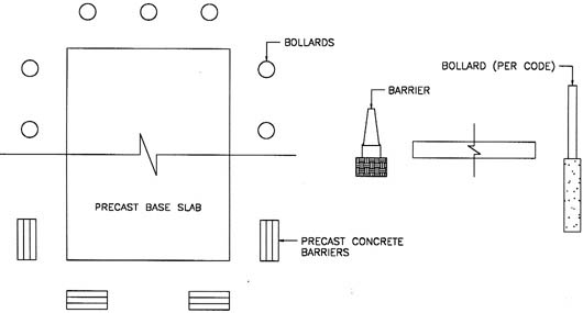
- Collision protection is recommended on the sides of the tank exposed to traffic. This is generally accomplished with pipe bollards. Always check state and local codes for specific requirements. See Figure No. 5 for sample installation.
- NOTE: The location of each ConVault® tank is stored in the central data bank. If the tank is to be relocated to a different location, ConVault® Inc. must be properly notified to update the data bank. The product limited warranty could be voided if ConVault® is not informed of tank relocation or if tank is not reinstalled in accordance with these installation instructions. It should be noted that ConVault® Warranty is conditional on installation of tanks in accordance with ConVault® Installation Instructions. Your attention is specifically drawn to the tank site selection and foundations requirements.
Foundations
- Tank location and foundation must comply with the current edition of Uniform Building Code requirements and all the applicable local codes and ordinances.
- An alternative to pouring the slab in the field is to purchase a precast slab from the manufacturer.
- The foundation for the tank must be designed to support the tank plus the weight of the maximum amount of product the tank will be storing. The foundation design must also include provision for draining surface water away from the tank to minimize the risk of fuel accumulation under the tank from the overfill or spills.
- Tanks located in areas subject to earthquake must be protected against seismic forces. Optional earthquake restraints are available. The restraints can be retrofitted to the slab should local requirements change. The restraints are mounted on the slab and are secured with anchor bolts directly into the slab. The tank feet rest in the restraints and do not require bolting directly to the tank.
- The tank located in areas subject to hurricane must be provided with hurricane hold down restraints.
- The tank foundation is to sit on undisturbed earth or compacted fill, free of organic material.
- The following minimum soil characteristics may be used if the ConVault tank is installed on a continuous solid slab which will uniformly distribute the weight of the tank and its contents to the soil:
- Bearing Capacity: minimum 1,000 but preferably 2,000 lb. per sq. ft.
- Total settlement: 1 inch maximum.
- Differential settlement: 1/2 inch maximum.
- Provide a minimum six inch (6") thick granular sub-grade, compacted and graded to a level uniform subsurface prior to the cast slab placement or pouring of the cast-in-place slab.
- A geological engineer should evaluate the effect of the water table and frost lines if such unusual conditions exist at the site.
- Soil surface under foundation should be flat within 1/16" per foot. Soil around foundation should be sloped away 1/8" per foot minimum for 5 feet.
- NOTE: If Bearing pads are used under the tank legs instead of grouting, the tank foundation and slab should be designed to withstand concentrated loads under the bearing pads.
- NOTE: The above soil characteristics, foundation and slab design requirements may be revised by a qualified design engineer who would design the foundations and the slab on a site-specific basis.
- NOTE: Some Authorities Having Jurisdiction require uplift restraints for areas subject to flooding and hurricanes.
Tank Handling
- DO NOT HANDLE OR INSTALL TANK WITHOUT HAVING KNOWLEDGE AND EXPERIENCE IN PROCEDURES INVOLVED WITH PROPER AND SAFE INSTALLATION OF AN ABOVEGROUND TANK USED FOR STORAGE OF STABLE, FLAMMABLE AND COMBUSTIBLE LIQUIDS. RELIANCE ON SKILLED AND PROFESSIONAL INSTALLERS IS AN IMPORTANT FACTOR IN AVOIDING DAMAGE TO TANK AND SYSTEM FAILURE.
- Equipment required in the shipping and offloading of ConVault® aboveground storage tanks include lifting straps, nylon tie-down straps, crane, forklift, and carpet remnants strategically placed on the bevels to prevent the tie-down straps from scraping the paint loose while the tank is en-route.
- Do not handle or move the ConVault unless it is empty. Under no circumstances should a tank containing petroleum product be moved.
- Do not drop or drag the tank.
- If petroleum product has been introduced in the tank, the tank must be emptied first, then may be relocated using the Department of Transportation Guidelines for transport of fuel containers. Normally, to relocate a tank previously containing flammable liquids, the Authorities Having Jurisdiction require the tank to be cleaned and then moved according to the following guidelines:
- Remove the liquids from the tank.
- Rinse the tank three times with an approved cleaning agent.
- Allow sufficient time for vapors to escape from inside of the tank.
- Move the tank under the supervision of the Authorities Having Jurisdiction.
Unloading and Setting
- The unloading equipment and procedures are critical to setting the tank safely and without harming the people or damaging the tank.
- NOTE: The most important aspect of a job procedure is SAFETY. Please ensure that every step of this procedure is carried out with safety in mind, first.
- Tanks Weight and Dimensions.
Please refer to Figures No. 2, 3 and 4 in Product Description. For actual tank weights and dimensions, please contact your ConVault distributor. - Equipment Required & Procedures
- A crane or a forklift of sufficient capacity to safely lift and place the unit.
- Slings minimum 20 feet long each and rated for the tank weight. The angles between the slings should be at least 50 degrees.
- 4-way spreader.
- Miscellaneous shackles, tag lines, and rigging tools.
- Plan the required crane and rigging capacity to safely unload the tank.
- Inspect the tank on the delivery truck prior to unloading. Report any damage in transit to the truck driver and note on the shipping ticket. If the tank is paint coated, it normally comes with two-1/2 pint, two-part touch up kits of paint. Please note that the touchup kit must be mixed prior to application.
- Allow sufficient crane time for installing the load block and organizing the rigging.
- During unloading and setting, allow one person in-charge to signal the crane operator. Keep people clear of the load and avoid being trapped between the load and building walls and equipment.
- Make sure there is no overhead wiring to interfere with crane or boom operation. Provide sufficient room for cranes and boom trucks to off load.
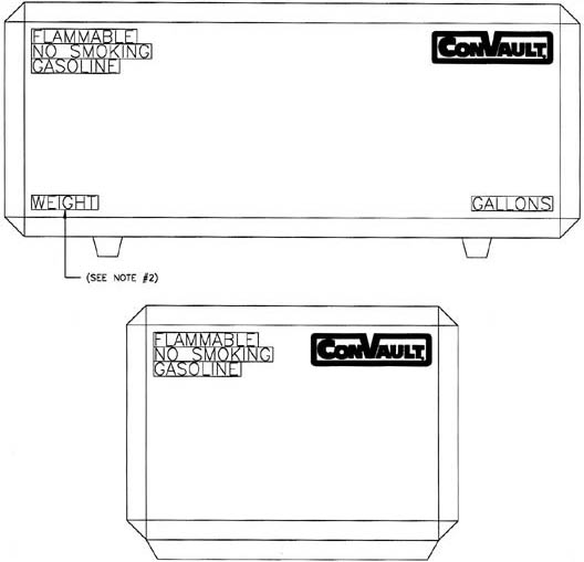
- Department of Transportation prohibits transportation of tanks with product and warning labels. Product and warning labels should be installed on site. If installed at the plant, they should be masked prior to shipment. Labels and decals must be placed on the tank in accordance with NFPA 709. Figure No. 6 shows location of labels.
Grouting of Legs
- All tanks of 4,000 gallon and larger must be grouted with (non-shrink grout) or supported with alternative engineered pad interface.
- We recommend to grout the legs of all tanks, which will provide a uniform load distribution on legs and foundations.
- Neoprene pads may be used instead of grouting in accordance with the manufactures recommendations. Also see Note under FOUNDATIONS.
Electrical
- Electrical service and fuel piping to the pumps unit should be installed in accordance with the requirements of NEC and NFPA and local code requirements.
- All electrical devices used with or located within twenty (20) feet of the ConVault® tank should conform to NFPA 70 Hazardous Locations. All electric conduits and wiring connected to the tank should be explosion proof and in strict accordance with NEC Class-1, Division 1 or other local standards whichever is stricter.
- An emergency shutoff switch is required to be mounted in a location visible from the dispenser. The switch is normally mounted on a building wall or a post. The per code switch must be marked as an emergency shutoff switch.
- Electrical grounding is required for flammable liquid fuel tanks. ConVault® tanks are provided with two grounding lugs welded to the nipples on tank top.
- Pumps and all other equipment used in the hazardous area should be rated by UL or Factory Mutual, FM.
Piping
- Piping on ConVault® tanks will mainly depend on dispensing method considered for your facilities. Several methods are suggested below. You should note that dispensing methods suggested here are schematic only and they are not detailed installation drawings. You should engage an engineer/designer to design the piping arrangement and make sure they are in accordance with the applicable codes, rules and regulations. Please also make sure you check with your Authorities Having Jurisdiction and find out which codes and regulations are applicable to your area.
- The following illustrations are provided to show you several different dispensing methods and to help you understand how they operate.
Dispensing Applications
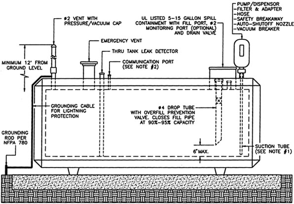
On-Tank Suction-Type
Dispensing from the ConVault® tank system is most simply accommodated by a top of tank pump. This arrangement eliminates leaking valves and fittings. Our recommended dispensing configuration is shown in Figure No. 7. Diagram provided is for those sites, which serve the end-user's internal fleet/vehicles.
- Fuel tank shall be located with set backs from building and property lines in accordance with state and local codes.
-
- vacuum breaker
- filter and adapter
- UL-Listed fuel hose
- safety breakaway valve
- auto-shutoff nozzle
- Consult local Authority Having Jurisdiction
- Fire extinguisher per code and cleanup kit should be provided at the site.
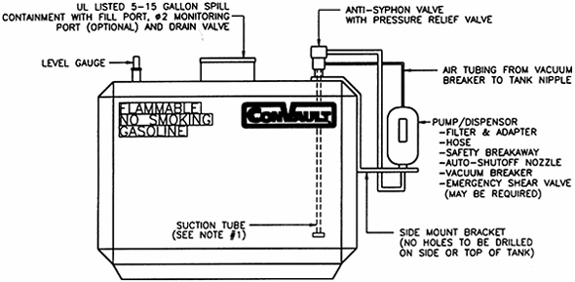
Side Mount
The diagram provided is recommended for the sites to dispense fuel to private user or for fleet vehicles. Figure No. 8.
- Fuel tank shall be located with set backs from building and property lines in accordance with state and local codes.
-
Dispensing shall be by UL-Listed pump. The pump shall be equipped with the following:
- Anti siphon valve with pressure relief or solenoid valve
- Filter and adapter
- UL-Listed fuel hose
- safety breakaway valve
- Auto shutoff nozzle
- Emergency shear valve may be required
- Consult local codes.
- Fire extinguisher per code.
- Cleanup kit should be provided at site.
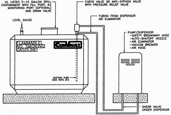
Off-Tank Suction System
The diagram provided is recommended for those sites authorized to either: dispense to motor vehicles for public use or fleet vehicles with high-speed dispensing accessories. Figure No. 9.
- Fuel tank shall be located with set backs from building and property lines in accordance with state and local codes.
-
Dispensing shall be by UL-Listed off-tank pump. The pump shall be equipped with:
- Angle check valve or anti-siphon valve with pressure relief
- Filter and adapter
- UL-Listed fuel hose
- safety breakaway valve
- Auto shutoff nozzle
- Under pump emergency shear valve (if required by local code)
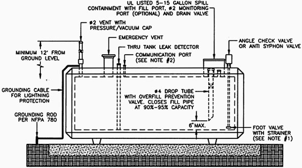
- Install pressure/vacuum vent cap.
- Install phase 1 and phase 2 recovery system (if required by the local codes).
- Consult local codes.
- Fire extinguisher per code, cleanup kit should be provided at the site.
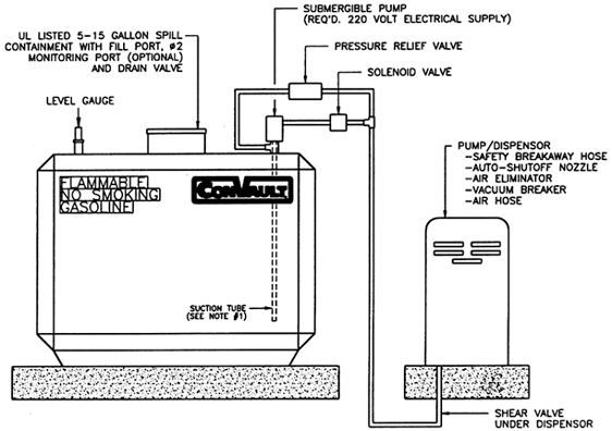
Submergible Pump
The diagram shown in Figure No. 10 is recommended for those sites authorized to either: dispense to motor vehicles for public use or fleet vehicles with high-speed dispensing accessories.
- Fuel tank shall be located with setbacks from buildings and property lines in accordance with the state, local, and fire codes.
- Dispensing shall be by an UL-Listed submergible pump.
- Solenoid valve with pressure relief valve.
- Filter and adapter.
-
UL-Listed dispenser with:
- Listed fuel hose
- Safety, breakaway valve
- Auto-shutoff nozzle
- Emergency sheer valve under dispensing pump may be required
- Fire extinguisher per code, cleanup kit should be provided at the site.
- Requires 220-Volt electric supply.
- Consult local codes.
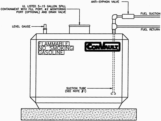
Generator Fuel Supply
The diagrams shown in Figure No. 11 and Figure No. 12are recommended for those sites utilizing a ConVault® AST to supply a generator, whether it is primary or standby in function.
- Storage tank shall be located with setbacks from buildings and property lines in accordance with state and local codes.
-
Recommended piping shall include safety valves as follows:
- Angle check valve with pressure relief or foot valve and strainer
- Shutoff valve with fusible link on supply piping
- Provide Anti Siphon Valve if the level of suction piping fall below the high level of fuel in the tank.
- Consult local codes.
- Fire extinguisher and spill cleanup kit should be provided at site.
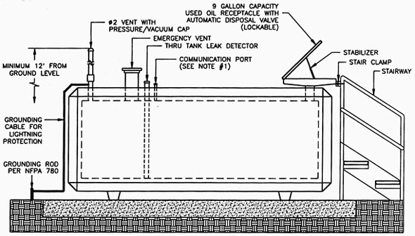
Generator Fuel Supply
The diagram provided is recommended for use with used oil storage and is not a requirement. Confirm with the local Authorities Having Jurisdiction and ensure that all pertinent operational requirements have been met in advance of installation. See Figure No. 13
ConVault® recommends the use of a used-oil receptacle, stair clamps, and a step-platform for manual pouring sites; where the tank is filled by a remote pump, an overfill prevention system should be utilized; ConVault® recommends the use of an audible alarm in conjunction with existing level indicator devices, as well as a solenoid valve in the fill pipe or shutoff switch to control the pump. Fire extinguisher and spill cleanup kit should be provided at the site.
Lighting Protection Installation Instructions
Grounding_Installation.pdf(guide to installation)List 1
Permits and Approvals
- Prepare state and/or local application forms.
- Prepare system detail drawings.
- Prepare system detail drawings.
- Draw to Scale
- Show property lines and indicate occupancy or use of adjacent property.
- Show streets, intersections, and railroads.
- Show buildings on the site and indicate type of construction. Show building openings on walls adjacent to tanks.
- Show important utility lines, sewer, water, gas, and electric including fire hydrants and catch basins.
- Show any nearby waterways, streams, rivers, lakes, or retention basins.
- Show any underground or aboveground tanks.
- Show new tank location and indicate shortest distance to buildings and property lines.
-
Prepare system detailed drawings to scale and show:
- Tank size, dimensions, and spacing between adjacent tanks.
- Base slab dimensions and bollard location and size.
- Vent size and location, including height of standard vent and type of cap.
- Fill details including spill and overfill protection.
- Piping details including shutoff valves and anti-siphon valves.
- Pumps and dispensing equipment including location, size, and type.
- Electrical details including shutoff switch location and grounding wire.
- Level gauges and leak detection equipment.
- Signs and decals.
- NOTICE: It is advisable for the owners/operators to become familiar with the codes and regulations applicable to their operation. Table 2 lists some of the codes and regulations governing aboveground storage tanks.
| Size | Length | Width | Height | Weight * |
|---|---|---|---|---|
| 125 | 4'-1" | 4'-1" | 3'-11" | 6,000 |
| 250 | 7'-8" | 3'-9" | 3'-3" | 8,000 |
| 500 | 11'-0" | 4'-6" | 3'-4" | 12,000 |
| 1000 | 11'-0" | 5'-8" | 4'-4" | 18,000 |
| 2000 | 11'-3" | 8'-0" | 5'-6" | 30,000 |
| 3000 LP(Low Profile) | 11'-3" | 8'-0" | 7'-3" | 30,500 |
| 4000 LP(Low Profile) | 17'-7" | 8'-0" | 6'-5" | 45,000 |
| 4000 DW | 12'-2" | 8'-0" | 8'-9" | 40,000 |
| 5200 G(General) | 15'-6" | 8'-0" | 8'-9" | 47,000 |
| 6000 | 17'-7" | 8'-0" | 8'-9" | 59,000 |
| 8000 | 23'-1" | 8'-0" | 8'-9" | 72,000 |
| 10000 | 28'-7" | 8'-0" | 8'-9" | 87,500 |
| 12000 | 34'-1" | 8'-0" | 8'-9" | 101,000 |
- The above sizes are typical, however some plants may not offer all tank sizes listed above. For additional sizes, or specific needs in your area, refer to your Convault® distributor/salesman.
- Double-wall steel tanks are optional and external dimensions are identical to single wall tank.
- Nipple layout and designs vary according to customer needs.
- NOTE: These are nominal weights of the tanks. Check with your distributor/salesperson for accurate weights.
Multi-Compartment Tank Weights and Dimensions *
The "D" Design
| Size | Length | Width | Height | Weight * |
|---|---|---|---|---|
| D250 | 11'-0" | 4'-6" | 3'-4" | 12,000 |
| D500 | 11'-0" | 5'-8" | 4'-4" | 15,500 |
| D1000 | 11'-3" | 8'-0" | 5'-6" | 30,000 |
| D1500 LP(Low Profile) | 11'-3" | 8'-0" | 7'-3" | 35,500 |
| D2000 LP(Low Profile) | 17'-7" | 8'-0" | 6'-5" | 45,000 |
| D2000 DW | 12'-2" | 8'-0" | 8'-9" | 40,000 |
| D2,600 G (General) | 15'-6" | 8'-0" | 8'-9" | 47,000 |
| D3000 | 17'-7" | 8'-0" | 8'-9" | 59,000 |
| D4000 | 23'-1" | 8'-0" | 8'-9" | 72,000 |
| D5000 | 28'-7" | 8'-0" | 8'-9" | 87,500 |
| D6000 | 34'-1" | 8'-0" | 8'-9" | 101,000 |
- The above sizes are typical, however some plants may not offer all tank sizes listed above. Other multi-compartment combinations are also available. For additional sizes, or specific application needs, please contact your Convault® distributor/salesman.
- Nipple layout and design vary according to customer needs.
- NOTE: These are nominal weights of the tanks. Check with your distributor/salesperson for accurate weights.
Multi-Compartment Tank Weights and Dimensions *
The "E" Design
| Size | Length | Width | Height | Weight * |
|---|---|---|---|---|
| E250 | 11'-0" | 4'-6" | 3'-4" | 12,000 |
| E500 | 11'-0" | 5'-8" | 4'-4" | 18,000 |
| E1000 | 11'-3" | 8'-0" | 5'-6" | 30,000 |
| E1500 LP(Low Profile) | 11'-3" | 8'-0" | 7'-3" | 35,500 |
| E2000 LP(Low Profile) | 17'-7" | 8'-0" | 6'-5" | 45,000 |
| E2000 DW | 12'-2" | 8'-0" | 8'-9" | 45,000 |
| E2000 G (General) | 15'-6" | 8'-0" | 8'-9" | 47,000 |
| E3000 | 17'-7" | 8'-0" | 8'-9" | 59,000 |
| E4000 | 23'-1" | 8'-0" | 8'-9" | 72,000 |
| E5000 | 28'-7" | 8'-0" | 8'-9" | 87,500 |
| E6000 | 24'-1" | 8'-0" | 8'-9" | 101,000 |
Sample Bollard Installation
Collision protection is recommended on sides of the tank exposed to traffic. This is generally accomplished with pipe bollards. Always check state and local codes. Sample installations are shown below:
Spacing from the tank should conform to code.
As an alternative to steel pipes, you may use precast concrete barriers. You can obtain the precast barriers from your ConVault® representative.
Figure No. 5
- FOR BEST RESULTS, ATTACH AT 60-70 DEGREES F.
- EMPTY WEIGHT
- CONVAULT LOGO DECALS TO BE LOCATED IN UPPER RIGHT CORNER OF ALL SIDES (QTY 4).
- NO SMOKING, FLAMMABLE AND "PRODUCT" TO BE LOCATED IN UPPER LEFT CORNER OF ALL SIDES (QTY 4).
- CAPACITY DECALS TO BE LOCATED IN LOWER RIGHT CORNER OF LONG SIDES (QTY 2).
- WEIGHT DECALS TO BE LOCATED IN LOWER LEFT CORNER OF LONG SIDES (QTY 2).
- FILL, VENT, EMERGENCY VENT, LEAK DETECTOR TUBE, DO NOT DRILL..., CAUTION THIS TANK..., DECALS LOCATED ALONG UPPER BEVEL NEAR CORRESPONDING NIPPLE.
- WARNING: DEATH MAY OCCUR..., DECAL TO BE LOCATED ON TOP OF TANK NEAR MANWAY IF APPLICABLE.
- BOTTOM OF FOOT VALVE/STRAINER TO BE 1" FROM BOTTOM OF STEEL TANK.
- COMMUNICATION PORT NOT NEEDED FOR DOUBLE WALL STEEL TANKS.
- STAIRWAY ASSEMBLY TO FILL PORT (OPTIONAL).
- BOTTOM OF FOOT VALVE/STRAINER TO BE 1" FROM BOTTOM OF STEEL TANK.
- STAIRWAY ASSEMBLY TO FILL PORT (OPTIONAL).
- BOTTOM OF FOOT VALVE/STRAINER TO BE 1" FROM BOTTOM OF STEEL TANK.
- STAIRWAY ASSEMBLY TO FILL PORT (OPTIONAL).
- BOTTOM OF FOOT VALVE/STRAINER TO BE 1" FROM BOTTOM OF STEEL TANK.
- STAIRWAY ASSEMBLY TO FILL PORT (OPTIONAL).
- BOTTOM OF FOOT VALVE/STRAINER TO BE 1" FROM BOTTOM OF STEEL TANK.
- COMMUNICATION PORT NOT NEEDED FOR DOUBLE WALL STEEL TANKS.
- STAIRWAY ASSEMBLY TO FILL PORT (OPTIONAL).
Generator Fuel Supply
For directions and side view see Figure 11
- BOTTOM OF FOOT VALVE/STRAINER TO BE 1" FROM BOTTOM OF STEEL TANK.
- STAIRWAY ASSEMBLY TO FILL PORT (OPTIONAL).
- COMMUNICATION PORT NOT NEEDED FOR DOUBLE WALL STEEL TANKS.
- STAIRWAY ASSEMBLY TO FILL PORT (OPTIONAL).


